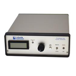
Single Output Scrambled Animal Shocker
Model HSCK100AP
This Shocker-Scrambler features a bipolar shock stimulus with eight pole scrambled output suitable for most behavioral applications.
This programmable shocker may be used to electrify the grid floor in an operant chamber, avoidance box or other shock motivated behavioral applications The output is an electronically controlled constant current of up to 5.10 mA with a resolution of 0.02 mA. The compliance voltage is 250 Volts. The output waveform is bipolar with a duty cycle of 12%. The scrambler has a cycle time of 75ms with each grid pair receiving a bipolar pulse of 8.3 ms. The shock output is isolated (floating) for the safety of the user and to minimize interference with any other equipment.
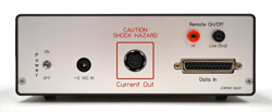
Shocker Back Panel View
Current Programming
The shock current can be programmed either manually with a front panel control or through a DB25 socket on the back panel that is compatible with the ABET II Interface product or any other product using an open-collector output that is shunted to ground in the ON state. TTL systems with an inverted or sinking logic (low level true) should also be useable. Data lines 0 - 7 represent a binary progression from 0.02mA to 5.10 mA in 0.02 mA increments. A separate trigger line is required. This unit is ideal for a fixed intensity trials or shock titration.
Shock Initiate Options
Shock output can be initiated with a front panel pushbutton switch, or by the trigger line described above for current programming. A pair of +/- pin jacks is also located on the rear panel. This initiate option can be configured to respond to a simple switch or relay closure, or configured to an optoisolator which can be driven by an Active HI voltage of 4.5 - 32 V Max with a minimum current of 2 mA. Internal jumpers are used to provide this last feature.
Grid Fault Test
One of the persistent problems of a grid shock apparatus is the gradual development of partial short circuits between grids due to the buildup of animal wastes. This can result in an attenuated and inconsistent shock current being delivered to the test animal, and consequently data with higher variability. The HSCK100A Programmable Animal Shocker incorporates circuitry which allows the user to test the shock grid for developing shorting faults. Pressing the front panel TEST switch initiates the grid fault test. The results of the test are indicated by a two color LED. The Grid Fault Test can also be initiated remotely through the rear panel DB25 connector. The results of the test are signaled by the front panel LED and by a signal pin on the DB25 connector.
Power Supply
The instrument is powered from a 12 VDC 500 mA wall mount power supply. This provides an additional safety feature as there is no direct AC mains connection to the unit.
Specifications
Kit Includes
- Grid Harness Cable
- Remote Initiate Cable
Dimensions
- L: 9.63”
- W: 7.38”
- H: 2.70”
Shocker Weight: 2.85 lbs
Cables Weight: 0.75 lbs
Power Requirements: 12VDC, 1.0A from a Switching Supply 100-240VAC